The process provides automatic band alignment and exposure balancing for imagery taken with a multi-camera rig system.
A multi-camera rig can acquire hundreds and thousands of image frames, each made up of multiple bands. Since each spectral band is taken by a separate camera, the resulting image bands are not correctly co–registered with each other. In addition, digital cameras are designed to automatically adjust shutter speed and ISO for each frame (based on the overall brightness of the scene), which means the resulting images have different exposures.
This process is designed to correct these problems in three operations: it performs multi-band alignment for each frame, exposure balancing from one frame to the next, and creates a contrast table for the set of images. The following analysis tools are available to help you set up the process and check the input and results at each step:
![]() View Track,
View Track,
![]() View Images,
View Images,
![]() View Histogram, and
View Histogram, and
![]() Image Band Correlation.
Image Band Correlation.
Processing of frames is extremely fast, typically requiring less than one second per frame after the initial alignment. A complete drone survey can be processed in the field on a laptop computer, typically in less time than the original flight. The process results in a corresponding output image for every input image. Note that resulting images are not georeferenced or mosaicked.
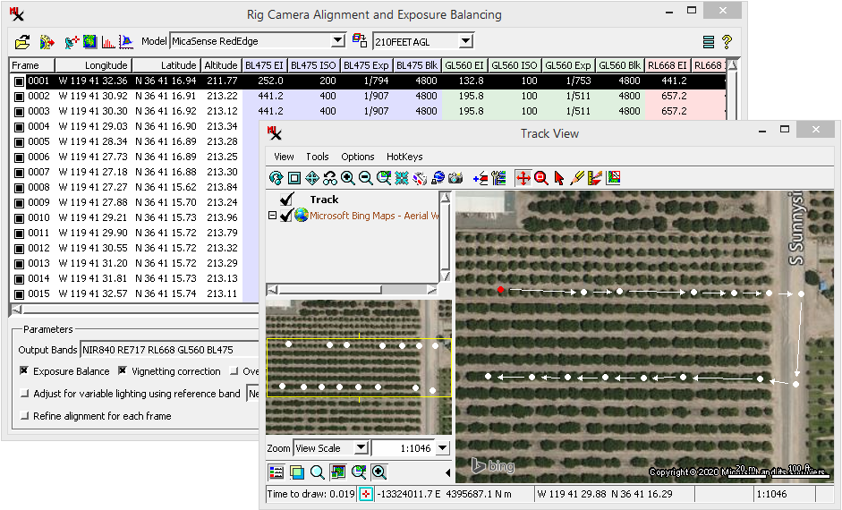
The selected frame is represented by the red dot in the window.
multi-camera rig — multiple, separate camera sensors on a UAS (drone) or piloted aircraft. Each camera is set up to capture a 'photo' for a specific spectral band (i.e red, green, or NIR wavelength range). The cameras are mounted together on a rigid frame and synchronized to take a picture at the same time. This set of photos taken at the same time is a single frame in the set of images acquired on the flight.
image — this process works with multi–band images, but generally speaking, an image for a given scene may be composed of one or more rasters for the same area on the ground.
frame — a single image in a series of images that were taken in sequence.
Imagery is collected along a flight path and each image has a frame number that indicates the order in which it was acquired.
In the context of acquiring aerial imagery, a 'frame' may also refer to the physical structure the cameras are mounted on.
co–registered — bands in a raster image are considered co–registered when they are co-aligned and features are correctly positioned (overlayed) in each band.
Prerequisite Skills: Displaying Geospatial Data and TNT Product Concepts.
Sample Data: Download the micasense_red_edge.zip file for use with the exercises included here. This data contain 15 frames from a MicaSense RedEdge camera rig.
The following five lessons walk you through the process from start to finish.
The basic steps to run the process are to: select the folder with input files, create or select the base alignment model, check if the model correctly aligns all the frames, and if so run the process.
Use the micasense_red_edge.zip sample data for the following exercises. See the Input section for information about acquiring imagery.
Tips: always select before input:
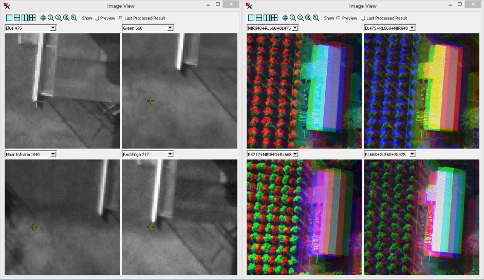
Frame number 0001 will be used to check alignment in the rest of the exercises as well. It has a building with straight edges that makes it easy to see how bands align.
Optionally exclude frame(s) from being processed:
a feature edge.
Look at the different cross–hair positions in each band (left). The same frame
is displayed
zoomed out on three–band composite layers also showing misalignment (right).
(continued from previous exercise)
(continued from previous exercise)
(continued from previous exercise)
If bands are still misaligned, you have options to: exclude the frame from processing (via the in the input frame list), recompute the base alignment model using a different input frame, or adjust the base alignment for each frame (via option). Then use ![]() again to replace or create a new base alignment model.
again to replace or create a new base alignment model.
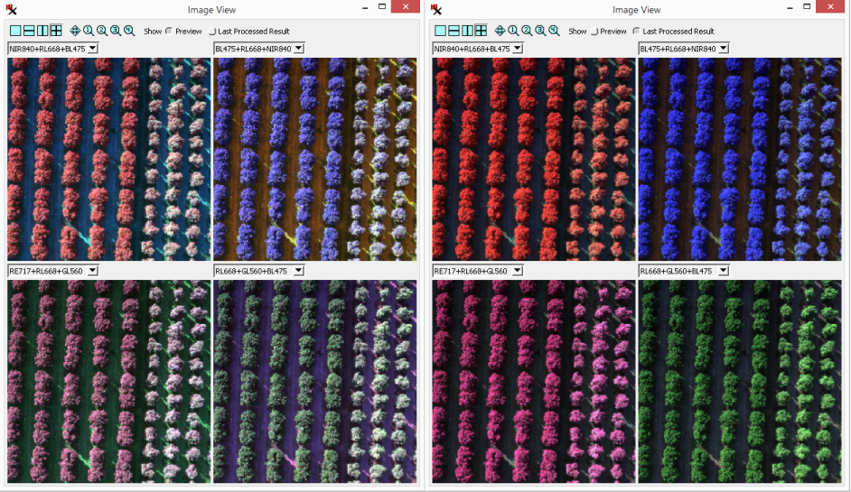
after running the process (right) have the same alignment correction. The difference
you see is
that exposure balancing and the contrast table have been applied to the final result (right).
(continued from previous exercise)
The time it takes to run depends on the number of frames to process. When the process completes, the window automatically changes to mode. Also note, if you reload input after processing, the mode is automatically available (as long as the output folder is still there).
This operation resamples bands in an image in order to correctly overlay features and co-align the rasters. Specifically, one band is used as the master and the other bands are adjusted to match it.
Imagery acquired from a multi-camera rig will have bands (in a single frame) that are slightly offset or misaligned with each other. First, a base alignment model is figured using a reference frame. The resulting model contains the adjustments needed to properly align the bands from all of the cameras. When the process is run the bands are resampled using the base model.
The band alignment operation is designed to work on imagery collected over a flat area at the same height above the ground. Before running the process on an entire set of image frames, you need to create a base alignment model that is specific to the camera rig and the height above ground (i.e. within a reasonable range of height values).
base alignment model — a rig–specific and height–specific model created that is used to automatically align bands in a set of images.
master camera — the process sets one camera as the master and figures out what adjustments are needed to align bands from the other cameras to it. For example, on a MicaSense rig the master is the NIR camera, which has the widest band width and is the sharpest image.
The image you use to create the base alignment model is an important consideration. In fact, a planned flight to take reference 'photos' is ideal. Choose an area that is flat and that has a lot of sharp spatial features over the entire scene (such as the lines on a parking lot). Acquire a separate reference image for any height you plan to acquire imagery at. Models created from a reference image can then be used for all imagery taken at the same height using the same camera rig. After you have the base alignment models you can correctly align any imagery you acquire even if it has no distinctive features.
Tip: when saving the model include the camera height (above ground level) in the name.
The exposure balancing step corrects for variations in exposure times and/or ISO settings from one frame to the next. It also corrects for vignetting.
When acquiring an image band, the camera records the brightness values of a patch of ground for a specific wavelength range. However, the cameras automatically adjust the shutter speed and ISO from one frame to the next based on the overall scene (i.e. more bright or dark features). This results in different recorded brightness values for the same feature, which is not desirable when using raster values as measurements.
(For example, imagine the same tree in two sequential frames, where one frame is much brighter overall than the other. The raster cell values for the same tree will not be the same in the two frames.)
Thus exposure balancing corrects for this by modifying the cell values accordingly. This operation assumes the amount of light from the sun is the same for all frames.
Contrast tables are also created for the resulting images and are automatically used when displaying them. The contrast table is identical for all frames and is computed based on overall range of values from all frames.
Analysis tools are available for the user to check input, preview base alignment model results, and study the final results.
Study the selected row (frame) in the input list via these analysis windows:
,
![]() View Images,
View Images,
![]() View Histogram, and
View Histogram, and
![]() Image Band Correlation.
In addition the
Image Band Correlation.
In addition the ![]() View Track option lets you see the flight path for all of the frames.
View Track option lets you see the flight path for all of the frames.
After creating or selecting a base alignment model, check that it correctly aligns the other frames in the input set. Use with the option and set it up to show multiple views (via ). Move cursor over the master band at feature edges and look at the corresponding crosshair positions over the other bands. Zoom in to verify the co-registrations are accurate.
Tip: display the master camera band in one view and compare it one–by–one to each of the other bands. Each band should be checked to make sure the alignment model correctly moves it relative to the master.
If the model results in a frame with misaligned band(s), you have options to: exclude the frame from processing (via the in the input frame list), recompute the base alignment model using a different input frame, or try to adjust the base alignment for each frame (via option).
Tip: look at the of the misaligned frame and see if it is within 20% of the intended height. If the height is not close enough to the others it will not correctly align the frame. Exclude frames at the start and end of your flight path if they have different altitudes.
The process input is raw imagery taken from a multi-camera rig system, where each band is acquired with its own sensor and lens (camera). Any number of frames taken in a single flight can be processed at the same time.
Imagery should be acquired within a narrow height range. Individual frames outside of this range, such as at the beginning and end of the flight path, can be excluded from processing. An accurate height is based on the camera's height above the ground. Note, the altitude shown in the input frame list is the GPS altitude, which is not the same as the camera height above ground.
If you don't already have a base alignment model (computed for the same rig and height) be sure to include an image with good feature edges that can be used to create one.
Input files must be stored in the folder structure specified by the camera model chosen. Each rig-camera system has their own specification on how files are organized and named. This structure determines what file corresponds to each band and the image track order (frame number). Supported multi-camera rigs include models from MicaSense, Parrot, MAPIR, SlantRange and SAL Engineering.
If your rig camera system is not listed, contact MicroImages about the possibility of adding it. In general, only commercially available (i.e., not custom–built) rig–camera systems will be included.
Choose the camera , then to load the imagery. Folders with imagery that are not from the selected rig will not be selectable.
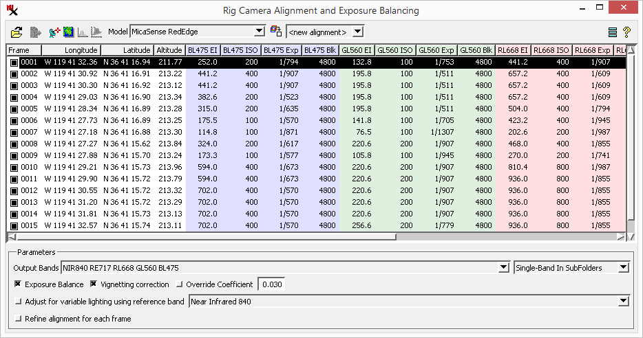
After selecting the input folder, each input frame is listed in order by frame number, which is computed based on the order it is added. If needed, exclude a frame from being processed by turning off the box near the frame number. The frame list includes columns showing EXIF information about each band in that frame including: longitude, latitude, altitude, exposure index (EI), ISO speed, exposure time (Exp), and black level (Blk).
The icon lets you choose what columns to show (i.e. ISO speed and exposure time).
Controls are available to set the output band order and specify the object/file structure. Choose to output images as multi-layer or multi-page TIFF files, or with each band in a separate file. The output folder and file naming conventions are set via the icon.
CRTIFF – contains camera-corrected and co-registered set of .tif files and a new GPSdata.csv file.
CRRVC – contains camera-corrected and co-registered .rvc files with the raster objects (linked to the corresponding .tif file in the CRTIFF folder).
'CR' is the default naming convention, which is an abbreviation for camera-corrected and co-registered images.
RigAlignSettings.ini – retains settings for the last run, which is saved in the same folder as the input images. This allows loading previous settings when using the input again and may also be used to find corresponding output. This file is specific to each datasets. This step usually takes 1-2 minutes depending on the number of cameras.
GPSdata.csv – contains GPS data in a format for use within photogrammetry software (i.e. Pix4Dmapper Pro or SimActive Correlator 3D)
![]()
![]() Open Folder – select folder with input files. Set the prior to selecting input.
Open Folder – select folder with input files. Set the prior to selecting input.
![]() Run – Use Run icon to generate output. After running, View Histogram and Image Band Correlation icons are available.
Run – Use Run icon to generate output. After running, View Histogram and Image Band Correlation icons are available.
The following options (in top toolbar) open analysis windows for evaluating input and result imagery:
![]() View Track,
View Track,
![]() View Images,
View Images,
![]() View Histogram, and
View Histogram, and
![]() Image Band Correlation.
Image Band Correlation.
– select the camera model from the list, which includes:
![]() Auto-Align – used to create a base camera alignment model using the currently selected image. Use to the base alignment model on the selected image. Click to replace or create a new base alignment model.
Auto-Align – used to create a base camera alignment model using the currently selected image. Use to the base alignment model on the selected image. Click to replace or create a new base alignment model.
![]() Settings
Settings
– add text to beginning of file name, default is 'IMG_'
– add text to end of file name, default is '_CR'.
– containing results. Default is 'CRTIFF'.
– containing results. Default is 'CRRVC'.
– name objects using Band Name, Band Abbreviation, or Band Code.
– name subfolder using Band Name, Band Abbreviation, Band Code, or Wavelength.
– append text to file name using Band Name, Band Abbreviation, Band Code, Wavelength, or Sequential options.
– when off, the user is prompted to choose the output folder after selecting .
– Metadata includes: Dimensions in pixels, Bit depth, resolution (DPI), Camera maker and model.
– if on, 0 cells will not be processed.
– show columns in input list.
– show column in input list.
– useful for single-sensor (Bayer-pattern) cameras. It lets you avoid listing duplicate columns in the main window since the exposure settings are always identical across all bands. (For true multi-sensor cameras like MicaSense this setting will have no effect.)
Each row represents a frame and shows columns with EXIF information for all of the bands (i.e. .tif files). Column backgrounds are color coded for quick band identification (i.e. red, green, blue, etc).
The listed metadata includes:
box – it includes right–mouse button options to: , and .
number – the sequence number for each input frame. It is set by the process in the order frames are listed.
– longitude and latitude of the aircraft at the moment the image was captured.
– GPS altitude of the camera above mean sea level in meters.
– Exposure index, which is a combination of exposure time and ISO setting. EI values change as the drone flies over different features (i.e. bright sand and dark water).
– ISO speed.
– Exposure time.
– black (Blk) values (dark current).
– by default there is an output for every input band. Select to specify the band number for each output band and/or choose to exclude band(s) from the output.
output to file or folder – , and .
– automatically compensate for exposure differences between frames. Such differences can be due to automatic
exposure adjustment on the camera when flying over bright versus dark surfaces. This improves matching of images while allowing the entire range of the sensor to be used.
– automatic vignetting / flat field correction when appropriate coefficients are available.
– enter a value between 0 and 1 to override (or supply if not available) the vignetting coefficient.
– compensate for variable lighting conditions using the selected band to adjust the others.
– used to adjust the base alignment for each frame. This fine–tunes each frame individually when the process is . Try this options if frames are taken at significantly different heights above ground. If on, process speed will slow down significantly.
Show GPS point locations over a suitable reference image (or Bing layer) to show the track flown and aid in excluding the beginning and ending images if needed.
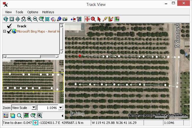
The red point indicates the selected input frame.
View automatically contrast enhanced combinations corresponding to the selected input image. Assign a spectral band to each of the display color components (red, green, and blue). Up to four views can be shown at once.
— preview the alignment correction using the selected base alignment model on the selected frame.
— after running the process, shows result for the selected input image. Alignment adjustment will remain the same for the frame used to create the base alignment model, however, it will look different since the contrast is applied.
Compare preview (pre-processed) and processed (aligned) frames in any 3-band combination or grayscale, with up to 4 simultaneous displays. Zoom in to see if co-registration is accurate.
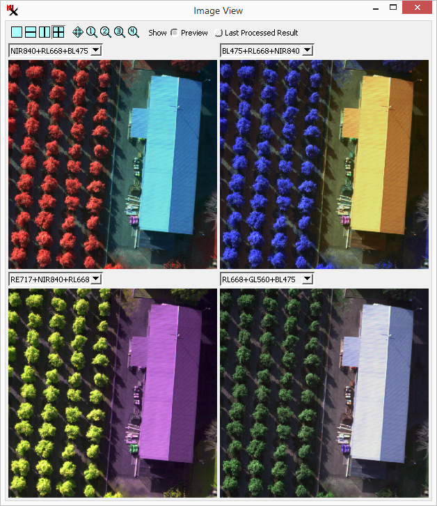
or use the option to set up a new composite layer.
Multi-band histogram with options to view a single selected input frame and/or the total histogram for all frames. When total and single histograms are displayed together, the Percent option for the graph's vertical scale gives you a way to compare them in the same graph.
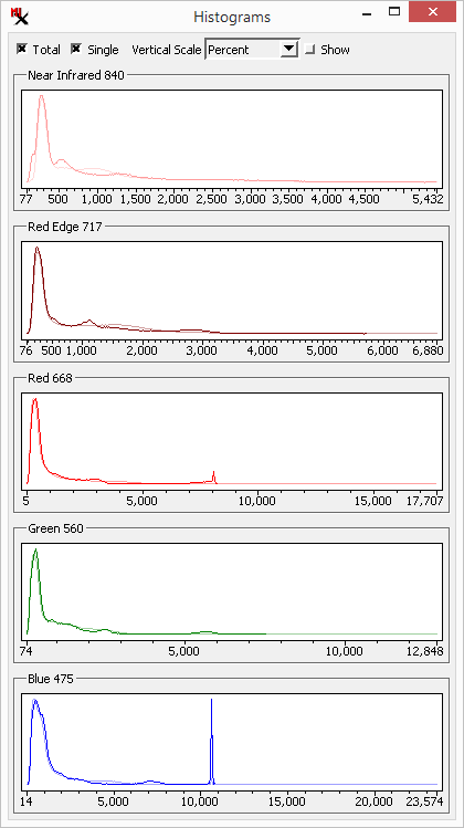
overlaid on the total for all images (fainter line).
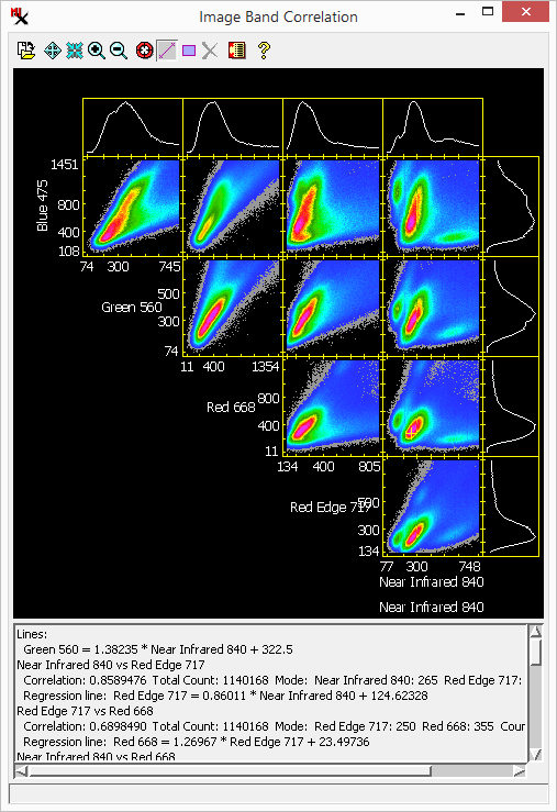
Image Band Correlation for the bands in the selected input frame, with automatic tracking of cell values based on cursor location in the image view window.