The process is used to create a distance and direction raster. A distance raster has cell values that represent the distance from features of interest in the input raster. Cell values in the direction raster indicate the direction towards the closest feature of interest relative to that cell location.
Features of interest are specified by cell value. An extra "margin" can be added to extend the output beyond the input raster dimensions. Output can be specified in cells or map units.
Prerequisite Skills: Displaying Geospatial Data and TNT Product Concepts.
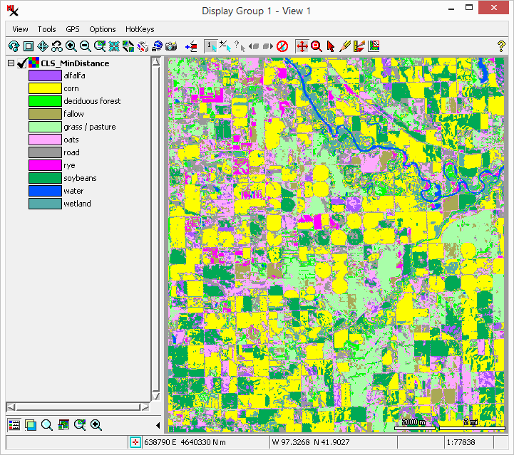
Sample Data: the stanton_class.rvc file in stanton.zip
Tutorial Lesson: The exercise below provides an introduction.
To run the process: load the input raster, set the cell value, and run.
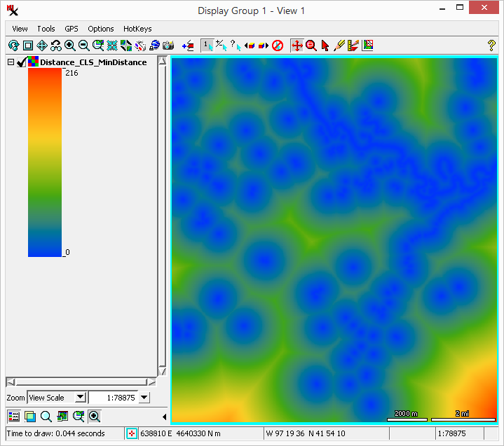
the orange are farthest away.
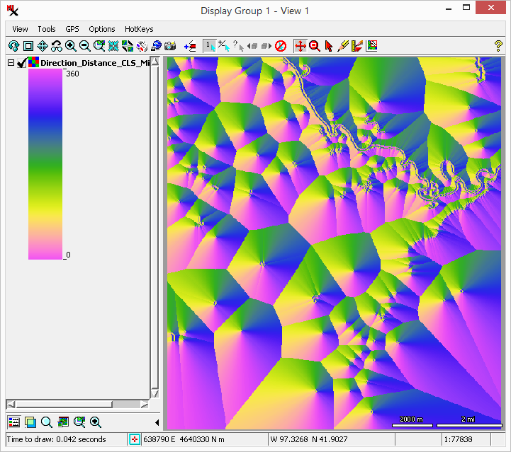
of pink cells (near 0 or 360) and south of green cells (near 180 degrees).
The process can take any raster data type as input (binary, signed/unsigned integer: 8-, 16-, and 32-bit; floating: 32- and 64-bit). The process requires the user to enter a cell value to specify the feature of interest.
The process outputs a distance raster and optionally a direction raster for every input rasters. Output rasters can be 32– or 64–bit data type. You have the option of setting a color palette to use when displaying it.
distance raster – has cell values specifying the distance to the nearest feature of interest.
direction raster – has cell values that specify the direction (0 to 360 degrees) towards the nearest feature of interest.
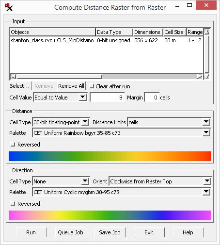
The is the main window used in the process.
Options here are used to select input and specify the feature of interest in it:
input list – selected input rasters are listed in rows with customizable columns showing information about each one. See also: Raster Input List for more information about using with the input list.
button – select input.
buttons – remove previously selected input.
toggle – clears input after running when on.
– choose the method and cell value to specify the feature of interest. Methods include: , and .
– add a margin around the raster to increase the output extents.
Options here are used to create a distance raster:
– 32– or 64–bit.
– for output cell values are in the number of cells or a conventional unit of measurement (i.e. meters, kilometers).
– menu to select color palette. The option opens the window. For best results, a cyclic palette is recommended to make the color changes continuous.
toggle – invert the color palette.
Options here are used to create a direction raster:
– 32– or 64–bit rasters as above, plus the option to not make the direction raster.
– determines the position cell value start at 0 and move towards 360 (degrees) in the clockwise direction. Choices are: , and .
Note, the cell value indicates the direction from the cell towards the closest features. For example, when is set to , 0 indicates the feature is above and 180 mean it is below.
– menu to select color palette. The option opens the window. For best results, a cyclic palette is recommended to make the color changes continuous.
toggle – invert the color palette.