The process is used to create a distance and direction raster. A distance raster has cell values that represent the distance from features of interest in the input raster. Cell values in the direction raster indicate the direction towards the closest feature of interest relative to that cell location.
Features of interest are specified by selected elements in a vector, CAD or shape object (or shape file). Output can be specified in cells or map units.
Prerequisite Skills: Getting Started and Displaying Geospatial Data.
Sample Data: the stanton_hydrography.rvc file in stanton.zip
Tutorial Lesson: The exercise below provides an introduction.
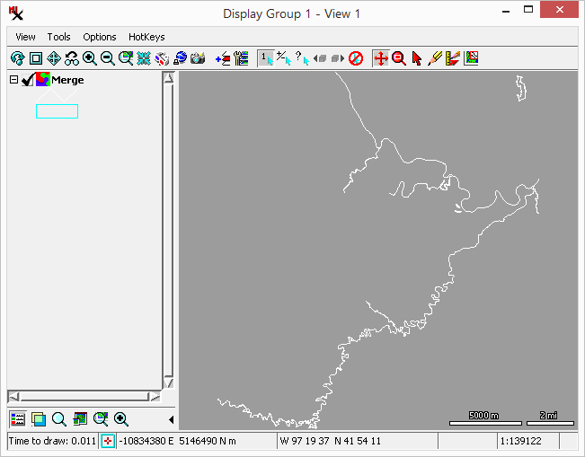
To run the process: load the input vector, specify elements to use, set output image grid, and run.
Notice the is set. The and are automatically set too.
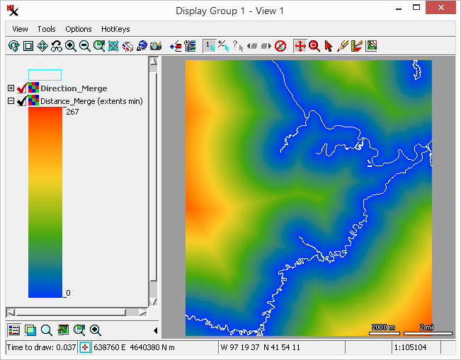
the orange are farthest away.
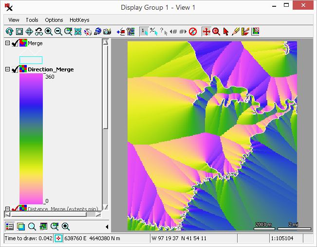
of pink cells (near 0 or 360) and south of green cells (near 180 degrees).
The process takes a vector, CAD, or shape object (or shapefile) as input. Then use the options to choose what elements you want to compute the distance from. For all input types, you have options to include all elements, elements selected in the , or elements selected via a database query. However, if the input is a vector you will first limit the element type to either point, line, or polygon.
The process outputs a distance raster and optionally a direction raster. Output rasters can be 32– or 64–bit data type. You have the option of setting a color palette to use when displaying it.
distance raster – has cell values specifying the distance to the nearest feature of interest.
direction raster – has cell values that specify the direction (0 to 360 degrees) towards the nearest feature of interest. The direction is aligned based on the setting. For example if you set to , then a cell value of 0 indicates the closest feature is in the direction towards the top of the raster. Cell values increase in the clockwise direction so for this example 180 points towards the bottom.
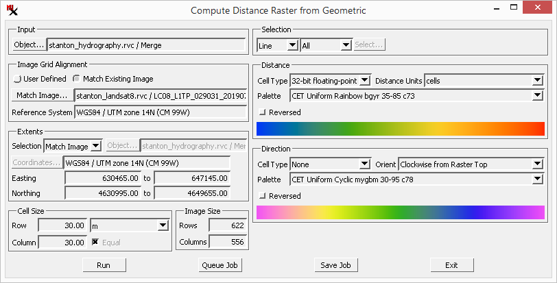
The is the main window used in the process.
– select a geometric object or shape file.
– select the elements to compute the distance from. You can specify the elements of interest using the , and options. In addition, vector objects require you to choose the type of element: , or . For more information, see the Geometric Element Selection section.
Specify the output raster's grid, extents, cell size, and image size using these four panes. For more information, see the Raster Grid Controls section.
Options here are used to set up the output distance raster:
– 32– or 64–bit.
– for output cell values are either the number of cells or a conventional unit of measurement (i.e. meters, kilometers).
– menu to select color palette used when displaying the distance raster. The option opens the window.
toggle – reverse the order of the palette.
Options here are used to set up the output direction raster:
– 32– or 64–bit rasters as above, plus the option to prevent making the direction raster.
– specifies the direction for cell value of 0. Thus this option sets up cell values with a specific direction — moving clockwise from 0 towards 360 degrees. Choices are: , and .
Note, a cell value indicates the direction from that cell towards the closest features. Example: if you set to , a cell values of 0 indicates the closest feature is above that cell (or below if 180).
– menu to select color palette for the output direction raster. The option opens the window. For best results, a cyclic palette is recommended to make the color changes continuous.
toggle – reverse the order of the palette.