Directional Analysis
V5.40 –– July 1996
 |
 |
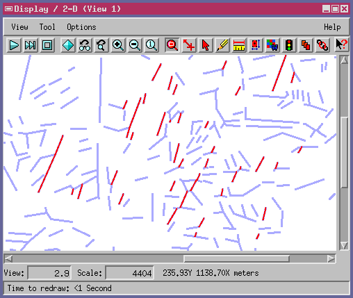
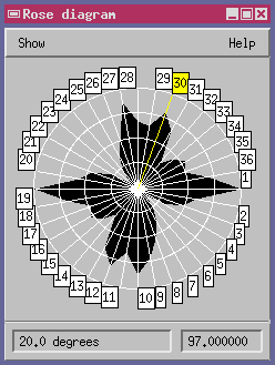
| Interactively selected lines with 20-degree orientation from North | Rose Diagram for direction selection |
A new Directional Analysis process in TNTmips (Interpret / Vector / Directional Analysis) analyzes lines in an input vector object for directional qualities. The process works in a "select by orientation" fashion: it highlights lines for viewing, or copies them to an output vector object based upon the line directional properties you specify.
In this version of the process, you can set orientation selection parameters either by entering values explicitly, or by clicking on directions in the accompanying Rose Diagram. The Rose Diagram window is logically a 180 degree arc that displays line orientation statistics in a centrally symmetric 360-degree presentation.
The process lets you set a Deviation value so that lines whose orientation is "close enough" to the selected orientation are also included. You can also adjust a Minimum Length value to exclude very short lines from analysis and processing.
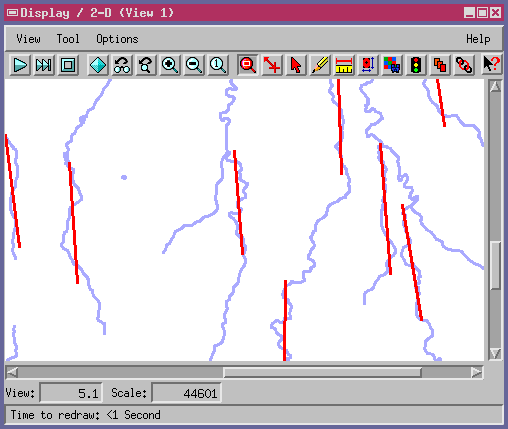
The Rose Diagram can display statistics for a number of directional properties of the input lines: Node to Node, Line Best Fit, Line Segments, Weighted Segments, Average Length, Angle Deviation, and Fixed Length contours. The following illustration shows how Line Best Fit determines a single direction for complex input line elements.

Display and output lines drawn with Line Best Fit and 10-degree deviation threshold
Directional Analysis, which is also called "Lineament Analysis", is used in a variety of applications. Geologists use directional analysis for fault line and fracture system analysis, and for many innovative topographic and lithographic analysis operations.